This site uses cookies to improve your experience. To help us insure we adhere to various privacy regulations, please select your country/region of residence. If you do not select a country, we will assume you are from the United States. Select your Cookie Settings or view our Privacy Policy and Terms of Use.
Cookie Settings
Cookies and similar technologies are used on this website for proper function of the website, for tracking performance analytics and for marketing purposes. We and some of our third-party providers may use cookie data for various purposes. Please review the cookie settings below and choose your preference.
Used for the proper function of the website
Used for monitoring website traffic and interactions
Cookie Settings
Cookies and similar technologies are used on this website for proper function of the website, for tracking performance analytics and for marketing purposes. We and some of our third-party providers may use cookie data for various purposes. Please review the cookie settings below and choose your preference.
Strictly Necessary: Used for the proper function of the website
Performance/Analytics: Used for monitoring website traffic and interactions
While many Architectural, Engineering and Construction firms use Bluebeam Revu to convert CAD to PDF, there’s an often overlooked capability that is as plain as the nose on your face. “Nowadays, I draw in Bluebeam equal amounts to sketching or CAD.” Let’s take a look at Nathan’s work.
Collaboration on large format construction drawings often has the expectation that all the team players have the same tools. Architects and engineers spend countless hours in AutoCad then share their drawings with the General Contractor. This is a sore spot for Architects and Engineers who are detail oriented.
Dezeen shares the project of design student Ken Nakagaki , who has adapted a device to work with computer aided design (CAD) software to replicate digital files on paper. Architects Building Owner BIM/IT Contractors Designers Engineers Facility Managers Building Team'
Imagine a robot, something like a combination Roomba vac and magic marker, that could translate complex construction drawings onto the ground, leaving an error-free map for building crews to follow. Architects Contractors Designers Engineers Building Technology' Body Image: read more.
Dezeen shares the project of design student Ken Nakagaki , who has adapted a device to work with Computer Aided Design (CAD) software to replicate digital files on paper. Architects Building Owner Contractors Designers Engineers Facility Managers Building Team'
Incorporate the Latest Project Management Software Computer-animated design (CAD) technology revolutionized design when it was introduced decades ago. All stakeholders have access to the same files, documents, drawing, and models. This includes everyone from architects, engineers, contractors, and subcontractors.
APA – THE ENGINEERED WOOD ASSOCIATION Multifamily Housing Engineered wood’s combination of benefits—from beauty and versatility to sustainability and strength—has made it a popular material for commercial projects such as mixed-use buildings, low-rise office structures and even eight-story mass-timber high rises.
Architects, Engineers and Contractors have standardized on the PDF as the file type to share, email and collaborate on. Everyday PDFs are instrumental in the construction conversation to show mark ups on Microsoft Office documents, interactively draw on tablet PCs and then share these PDFs on Servers.
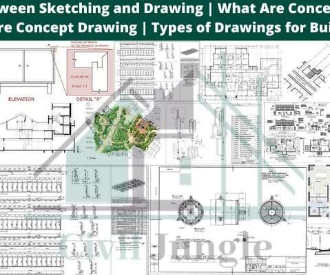
Conceptual Sketches are freehand sketches that are used by designers such as architects, engineers, designers as a quick and simple way. Architecture Concept Drawing. An architecture concept drawing is a technical drawing of a building (or building project) that falls within the definition of architecture. Perspective.
In 1970 (some of us lived in ancient times), I was a graduate engineer responsible for purchasing millions of dollars of production equipment for Chevrolet engines. We were engineers – what the heck did we know about safety? What I rarely see is something that the writer actually put into practice.
Introduction of Civil Engineer Software: There is multifarious software accessible which are utilized in Civil Engineering. The Civil Engineering Softwares are surging manifold day by day. Here could be a list of SOFTWARE which are outrageously employed by many Civil Engineers all round the world. Software for Surveying.
After reading “Collaborating in the New AEC World” by Al Douglas it is apparent that whether you are a subcontractor, general contractor, architect, engineer or project owner you must have a single place to effectively communicate in order to reach all project team expectations. It’s challenging and frustrating.
East Coast CAD Kicks it up a Notch. East Coast CAD has had Fabrication for AutoCAD MEP software for years, but it added MEP Fabrication Version 1.0 See East Coast CAD announcement here. 25th at 1PM EST. There is a sign up link from the EastCoast CAD/CAM home page. CAD Shack VIPs. CAD Shack Blog Buddies.
There are new features and enhancements in Autodesk Revit 2015 R2 dedicated especially to structural engineers. You can snap to an imported and non-exploded CADdrawing. Similar to the behaviors when placing structural walls and slabs, all structural elements now snap to the geometry of imported drawings.
As recently as yesterday, a consultant looked at me genuinely surprised that I expected from him rapidly coordinated architectural and structural drawings following client initiated changes to numerous floor levels within the project.
The shop drawing is a drawing or collection of set of drawings, diagrams, illustrations, schedules, and other data or information specifically generated or assembled by the contractor, supplier, manufacturer, subcontractor, or fabricator to demonstrate some portion of the work for the approval of architect or engineer.
Because you need to own the drawings to have sufficient access to the CAD objects, or be on a truly team-oriented project that shares its resources openly among all project players. Additionally, built-in clash-detection attributes prohibit drawing ducts through windows, or electrical lines through ducts. Why Design-Build?
Plans are like a set of drawings or two-dimensional diagrams that are used to narrate a place or object or to communicate building or fabrication instructions which are drawn or printed on paper and can take the form of a digital file. So these design drawings can be categorized as: • Feasibility studies. Concept drawings.
If you are coming to Revit MEP from AutoCAD or AutoCAD MEP, you may be very used to specifying a duct system when you draw duct. I am the BIM Manager for Alvine Engineering, a college instructor and the Revit MEP Content Manager for AUGIWorld Magazine. CAD Shack VIPs. CAD Shack Blog Buddies. RobiNZ CAD Blog.
The idea is to draw a generic annotation shaped like a lasso and add a leader to it, but set the leader arrowhead to none. Draw a line centered on the intersection of the reference planes then an arc above and another arc below. CAD Shack VIPs. CAD Shack Blog Buddies. RobiNZ CAD Blog. The MEP CADEngineer.
The Draw MEP Hidden Lines box is checked in the Electrical Setting s dialog. I am the BIM Manager for Alvine Engineering, a college instructor and the Revit MEP Content Manager for AUGIWorld Magazine. CAD Shack VIPs. CAD Shack Blog Buddies. RobiNZ CAD Blog. The MEP CADEngineer. Todd Shackelford.
Melinda Heavrin’s article “ Collaboration with Autodesk Design Review ” elaborates on how drawing markups can become an easy, streamlined operation. I am the BIM Manager for Alvine Engineering, a college instructor and the Revit MEP Content Manager for AUGIWorld Magazine. CAD Shack VIPs. CAD Shack Blog Buddies.
This week I needed to create some structure from the structural engineers AutoCAD plans since they were not using Revit. The way I got around the above mentioned error was to open a structural model I received from a different engineer on a different job. It shows up fine in my drawing and I can change its length, offset and location.
CAD Employee Hiring 101 – The fundamentals of hiring CAD employees are often overlooked. I am the BIM Manager for Alvine Engineering, a college instructor and the Revit MEP Content Manager for AUGIWorld Magazine. CAD Shack VIPs. CAD Shack Blog Buddies. RobiNZ CAD Blog. The MEP CADEngineer.
This construction video provides the detailed lists of most recognized design and analysis software for Civil Engineering. For more information, visit www.csiamerica.com GT Strudl – It is a powerful structural analysis and design modeling software for structural engineers.
This is the third blog post in a series that discusses the advantages of working on concrete projects in a BIM process for structural engineers. Segmentation is dictated by engineering, architectural, or fabrication requirements, and its reinforcement is determined by the structural engineer.
First thing, first: “The survey asked a series of questions to establish current usage of both 2D and 3D CAD, as a precursor to determining likely future engagement with Building Information Modelling (BIM).” … actually, this was the question: “When producing CADdrawings, which of the following tools do you mainly use?”
This approach is somewhat surprising considering that in most contemporary construction contracts PDF’s as the digital representations of drawings have often higher standing than model files or even DWGs. One would presume a chunky market to be there for developers of PDF focused tools.
Architects, Engineers, Specialty contractors, Material Suppliers and Owners love it. Impromptu Problem Solving in the field with access from your iPad to photos captured of current conditions and access to sketch and markup with engineers, designers, etc. ”, all over again. Use Studio to save time and improve productivity.
This video is very useful civil engineers. It consists of structural calculation report, construction drawing having bar schedule, material quantities and 3D CAD modeling. This construction video provides brief guidelines for the design for tank foundations with AFES foundation design software.
It started off with CAD, then, when BIM was getting strong enough to stay – it extended over almost anything to do with Construction Information Management. Ever since the first CAD hit the market, there had been viable alternatives for users to chose from and by doing so keep competition live and the suppliers honest.
PRWEB) November 22, 2011 — Today AViCAD.com announced the addition of their new Architectural software which will facilitate the architect, engineer or designer with drawing 2D floor plans and roof designs. Easy-Arch includes set of utilities to draw walls , windows, doors. Bend Oregon, U.S.A.
The document is typically composed of the following: A narrative or written document outlining how the various components will be approached Drawings and illustrations indicating temporary construction and phasing Photographs and images A detailed or milestone construction schedule. Include a drawing of your site safety plan.
Consider this: you are a confident consultant (architect, engineer) prepared to stand up publicly and say: “No, we do no BIM in our office and are proud of it! We produce documentation for our buildings ‘the good old way’ and use CAD where absolutely necessary and only to mimic the traditional processes.
There’s a gentleman I know of, who went from being ‘just’ a CAD manager in a public company to becoming the Head of Information Services of a large entity, and getting charged with writing the BIM specification for a huge project. Another day, when a CAD Manager has seized the power. And, I mean HUGE project!
ETABS combines each phase of the engineering design process from initial design perception to the formation of schematic drawings. With superior drawing commands, one can instantly generate floor and elevation framing. With superior drawing commands, one can instantly generate floor and elevation framing.
The industry has been doggedly-loyal to the misguided belief that some sort-of-risk management is being exercised when CAD files are not issued out. talking Flatcad here, not models!). Instead we get PDFs. Consequently, our guys are constantly crying out for converters. There is no shortage of them on market.
The structural engineer sizes the concrete column; the architect places it in the space. There is a code on the structural drawing that can be tracked to the schedule and the dimensions are noted. They both are confident to be following well established building-documenting practices.
PlanGrid, the most recognized CADdrawings viewer and cloud -collaboration tool in AEC, recently launched a dedicated all-in-one RFI solution that will provide immense benefits to the architecture, engineering and construction (AEC) industry. construction construction material engineering News'
Here the calculation is carried out by associating the drawing to the HTML section. The drawing of entities are created on the plan while exploring on a CADdrawing. Based on the formula provided to the item, the linear value of your phase value is impacted automatically.
Computer Aided Design (CAE) goes beyond CAD. In the manufacturing world, PLM, product lifecycle management (PLM) is the process of managing the entire life-cycle of a product from its conception, through design and manufacture, to service and disposal.
Engineering firm Melia Smith & Jones uses SOFiSTiK software for 3D rebar modelling in Autodesk Revit. Most engineers still produce classic 2D reinforcement drawings using programs such as AutoCAD ® combined with CADS RC. SOFiSTiK involves the annotation side when creating reinforcement drawings in Autodesk Revit.
Orion is a construction program as well as structural engineering software from CSC (currently acquired by Tekla) that can be used for developing efficient structural design. This is a useful construction video that shows how to use Orion V18 software to create the design of a basic structure.
These are very valid questions that many CAD Managers and Owners are asking themselves lately. Compatibility At last, I can open any ADT drawing file without issue. More Design less Draft Engineering data in the DWG is used as a graphical tool that speeds the design process and highlights trouble spots.
We organize all of the trending information in your field so you don't have to. Join 116,000+ users and stay up to date on the latest articles your peers are reading.
You know about us, now we want to get to know you!
Let's personalize your content
Let's get even more personalized
We recognize your account from another site in our network, please click 'Send Email' below to continue with verifying your account and setting a password.


Let's personalize your content