This site uses cookies to improve your experience. To help us insure we adhere to various privacy regulations, please select your country/region of residence. If you do not select a country, we will assume you are from the United States. Select your Cookie Settings or view our Privacy Policy and Terms of Use.
Cookie Settings
Cookies and similar technologies are used on this website for proper function of the website, for tracking performance analytics and for marketing purposes. We and some of our third-party providers may use cookie data for various purposes. Please review the cookie settings below and choose your preference.
Used for the proper function of the website
Used for monitoring website traffic and interactions
Cookie Settings
Cookies and similar technologies are used on this website for proper function of the website, for tracking performance analytics and for marketing purposes. We and some of our third-party providers may use cookie data for various purposes. Please review the cookie settings below and choose your preference.
Strictly Necessary: Used for the proper function of the website
Performance/Analytics: Used for monitoring website traffic and interactions
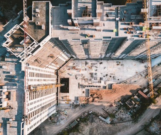
This has obviously led to large-scale improvements in the way structures are designed and building materials are fabricated. All stakeholders have access to the same files, documents, drawing, and models. As in all walks of life, technology and innovation are changing the landscape of the industrial construction industry.
Having a more accurately defined design model in Revit also enables a better interoperability with Advance steel for steel detailing and fabrication. Documentation with steel details. You can use a set of dedicated tools to create precise and detailed engineering drawings where steel connections are represented accurately.
In the construction industry, shop drawings play a crucial role in the execution of projects, providing detailed illustrations and specifications for components and assemblies. This article explores what shop drawings are, their significance in construction, and how they facilitate seamless project execution. What are Shop Drawings?
The shop drawing is a drawing or collection of set of drawings, diagrams, illustrations, schedules, and other data or information specifically generated or assembled by the contractor, supplier, manufacturer, subcontractor, or fabricator to demonstrate some portion of the work for the approval of architect or engineer.
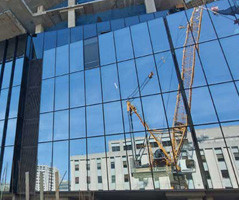
Technological advancements in curtain wall design tools, materials, prototyping, and fabrication techniques offer new avenues for achieving these lofty design and performance goals. The architectural design of curtain walls must be developed alongside increasing demand for high-performing, energy-efficient solutions.
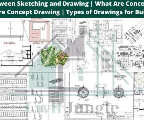
Concept drawing can also be used to explore more technical aspects of a design providing an initial response and possible solutions to problems, constraints and opportunities such as service layout, structure, method of construction, paths and shading, patterns and calculations, the relationship between aspects of size etc. Scale Drawing.
If a picture can speak a thousand words, in a project, as-built drawings can speak a thousand construction processes. But in all seriousness, with the hundreds and thousands of steps and documents needed to complete just one project, as-builts might be overlooked for their importance. Shop drawing changes. Key Takeaways.
2) poor communication between the fabricators and erectors. (3) 8) inadequate preparation and review of contract and shop drawings. (9) 3) Bad workmanship, which is often the result of failure to communicate the design decisions to the persons, involved in executing them. (4) 9) poor training of field inspectors. (10)
Its importance is evident when you consider that the cost of fabrication, erecting and striking the formwork, often exceeds the cost of the concrete it is designed to shape and support. For anything other than most smallest of concreting jobs e.g. walls over 1m in height, a drawing should be provided, showing what formwork is required.
The submittals include samples, drawings, project data, material listings, quality assurance, etc. Many types of documents during construction make up submittals. In most cases, project managers usually attach these documents or submissions to the project manual for easy accessibility and to provide information to all stakeholders.
The submittals include samples, drawings, project data, material listings, quality assurance, etc. Many types of documents during construction make up submittals. In most cases, project managers usually attach these documents or submissions to the project manual for easy accessibility and to provide information to all stakeholders.
The submittals include samples, drawings, project data, material listings, quality assurance, etc. Many types of documents during construction make up submittals. In most cases, project managers usually attach these documents or submissions to the project manual for easy accessibility and to provide information to all stakeholders.
The latest version of Advance Steel adds a host of new features and enhancements that help improve productivity and usability, and allow fabricationdocuments to be drafted and documented more easily to support BIM enabled workflows. Easy Access to Fabrication Data. Documentation Improvements Productivity and Appearance.
Sometimes, as you know, project documents can devote an entire plan sheet or spec section to a list of abbreviations and acronyms. A lot of this communication revolves around the project documentation. document management. ALICE is one of my favorites of the 205 Official Army Acronyms. The construction industry is no different.
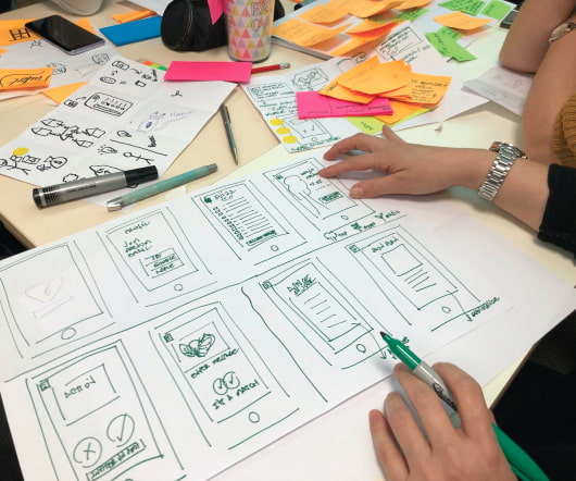
Drawings have been used by designers for centuries to communicate ideas to the construction trades. Until recently, those drawings were produced by hand, but in the last 25 years or so, computers have become the primary tool people use to produce construction documents. BIM & Pre-Fabrication. document management.
Construction submittals are documents provided by a contractor to an architect for an approval of use. The submittal log includes information provided to the architect asking for approval for certain materials and equipment before they’re fabricated and sent to the project site. What is a submittal? Color and finish selections.
Plans are like a set of drawings or two-dimensional diagrams that are used to narrate a place or object or to communicate building or fabrication instructions which are drawn or printed on paper and can take the form of a digital file. So these design drawings can be categorized as: • Feasibility studies. Concept drawings.
The metal should have good workability but also keep its strength during fabrication. Green part in the drawing represent restraint fixing and blue part as load bearing fixing. Non standard materials are difficult to purchase and also very expensive.
They see trends toward integrating information better, both with building information modeling (BIM) and drawings, and between teammates. He sees reliance on the full-time specifier continuing, but bridges being built slowly between that person and the drawings. They imagine specifiers will be increasingly integrated with their teams.
For this post, I’m going to summarize some of the Advance Steel tips and tricks that I described in my class “Advance Steel Tips, Tricks, and Workflows You’ll Want to Try at the Office” during the Autodesk University MEP & Structural Fabricators Forum 2017. Using specific colors for parts on drawings. Center of Gravity.
And, teams in the field can access project data direct from mobile devices instead of calling into the office and asking for specific numbers or documentation. HR and Payroll: Online portals streamline the recruiting and onboarding processes , and allow for employees to upload time, request time off and manage documents and more.
Additionally, our efforts are also focused on making steel detailers and fabricators connected across detailing service providers, fabricators and BIM process stakeholders. We continue to look forward to improving the quality and reliability of Advance Steel especially in the area of drawings and documentation.
The Martin/Martin CES team has innovatively addressed the issue of fragmented fabricationdrawing production that design and construction teams consistently encounter with today’s increasingly tight project delivery schedules. This process allows delivery of the first package of shop drawings (reviewed and approved!)
An eventual goal might look like an integrated AI overseer that combines all these risk identification capabilities, or a system automating code compliance, document consistency and cost tracking that could help teams mitigate issues and avoid surprises.
Before we dive in, let’s quickly review the four benefits of BIM for engineers: Combines the versatility of 2D documentation with the higher level of fidelity and accuracy of 3D modeling of steel reinforcement and concrete accessories, with minimal effort to produce both. Take, for example, a precast concrete wall. Custom rebar lists.
In construction, a Request For Information (RFI) seeks the clarification of plans, drawings, specifications, and agreements. The construction RFI is a formal written process in which parties, such as the contractor and designer, clarify information gaps in construction documents.
I have rarely read a construction blog post with as much power and impact as this recent Procore Blog post: Inside theRisks of Construction Drawings: The Case of the Hourglass , by Bridget Johnson. The sub responsible for the structural steel ignored the mark and showed standard joist girders on the shop drawings.
Model views combined with cameras help simplify the process of creating general arrangement drawings. Advance Steel 2018 now enables you to combine a model view with a camera and use it for drawing creation by assigning it a specific drawing style & scale. 4 – Call out on drawing. 4 – Call out on drawing.
Adding Autodesk Build to their construction solution stack enables Boustead to implement an effective IDD framework process with a single source of truth for the entire building lifecycle to ensure that Revit BIM models, drawings, RFIs, and document submissions by different stakeholders are shared effectively. to 1.5hrs).
Fortunately, you can overcome these hurdles by using ACC Connect to sync drawings, field reports, and documents in the cloud. And since the information stays in sync, teams know that they can get the documents and information they need in the application they use most. . 2: Project Management. 4: Performance Tracking.
Throughout the ongoing process, however, all of the following are address and/or improved upon: Who can offer change ideas (informally and formally) Who assesses the impact of the proposed change Who reviews the proposed change and its impact for approval How is the change implemented Documentation of the outcome. enables full visibility.
During the project process from design to detailing, there are many discussions between engineer, detailer, and fabricator about how to connect the multi-material framing elements like beams, columns, and bracings.
The following template is provide for sample purposes only and should not be used a legally bidding document without through review and modification by appropriate Owner legal counsel. Architect/Engineer’s Guidelines, Quality Control, and other related documents in effect at. JOB ORDER CONTRACT (JOC) EXECUTION GUIDE. the time of award.
By broadening design to anticipate construction issues and delivering a fabrication-ready model, engineers can create more certainty in cost, schedule, and design intent. In general, the higher LOD numeric value, the further along that element is on the spectrum from concept to fabrication ready.
This civil engineering article sheds light on the inspection method of various civil works as well as necessary documents to carry out an inspection at construction project. Construction activities and consequent inspection standard should be based on job site specifications, methods and drawings.
This construction estimating sheet is not intended for conventional usages the same as an engineering or construction document. Steel Surface Area Estimation Spreadsheet While preparing this estimating spreadsheet, suggestions was taken from the American Institute of Steel Construction, Inc.,
In this article, we will explore key terms such as sustainable construction, turnkey projects, and as-built drawings, with helpful links that provide in-depth insights. What are ‘As-Built Drawings’? As-built drawings are indispensable for facility management, maintenance, and any subsequent renovations.
BIG STUFF New Features Videos - Start with these videos provided as part of the help documentation if you prefer watching videos to reading my blog post. Occlusion Culling (2016R2) - The Graphics tab in the Options dialog offers the new setting: Draw visible elements only. Okay, on to the list! has finally been tackled.
ABT Netherlands, a multi-disciplinary consultancy firm, focused on the structural engineering, civil engineering, architectural engineering, moved to BIM-based 3D rebar for concrete reinforced design and fabrication as a result of client demand. Their use of Revit and SOFiSTiK on the Moorgate Shaft project is well documented.
Obviously it won't really do the job for fabrication or construction documentation. If you want a fast way to "draw" millwork a railing works pretty well. Back to the idea of millwork. Railings are based on profiles, so are cabinets, at least when you are being really schematic.
If you’ll remember, I’ve described what I see as four main benefits for a BIM-centric approach to concrete: Combines the versatility of 2D documentation with the higher level of fidelity and accuracy of 3D modeling of steel reinforcement and concrete accessories, with minimal effort to produce both.
Common construction abbreviations as as part of cost estimating software, Job Order Contracting software, and construction documents is a standard practice. DWG: Drawing. DWGS: Drawings. FAB: Fabricate. FABR: Fabricate. FBP: Fabric Panel. VF: Vinyl Fabric. WWF: Welded Wire Fabric. DWL: Dowel.
In 2005, Kory Bieg founded OTA+, an architecture, design, and research office that specializes in the development and use of current, new, and emerging digital technologies for the design and fabrication of buildings, building components, and experimental installations. As this moves forward, it will begin to impact this condition.
They may be the brightest, but lack practical experience and tend to create obtuse documents no-one else but fellow academics can comprehend. So Standards invariably document out of date practices in a manner that can not be understood by those who are supposed to follow them. BIM is PROCESSES.
We organize all of the trending information in your field so you don't have to. Join 116,000+ users and stay up to date on the latest articles your peers are reading.
You know about us, now we want to get to know you!
Let's personalize your content
Let's get even more personalized
We recognize your account from another site in our network, please click 'Send Email' below to continue with verifying your account and setting a password.


Let's personalize your content