This site uses cookies to improve your experience. To help us insure we adhere to various privacy regulations, please select your country/region of residence. If you do not select a country, we will assume you are from the United States. Select your Cookie Settings or view our Privacy Policy and Terms of Use.
Cookie Settings
Cookies and similar technologies are used on this website for proper function of the website, for tracking performance analytics and for marketing purposes. We and some of our third-party providers may use cookie data for various purposes. Please review the cookie settings below and choose your preference.
Used for the proper function of the website
Used for monitoring website traffic and interactions
Cookie Settings
Cookies and similar technologies are used on this website for proper function of the website, for tracking performance analytics and for marketing purposes. We and some of our third-party providers may use cookie data for various purposes. Please review the cookie settings below and choose your preference.
Strictly Necessary: Used for the proper function of the website
Performance/Analytics: Used for monitoring website traffic and interactions
Building on Autodesk’s strategy to make Revit a robust model authoring tool for designing and detailing, the Revit 2019 release includes a number of new features that increase modeling versatility, accuracy, and productivity for engineers and detailers. We’re excited to share these features with you—take a look! Detailed Steel Design.
Even experience in extensive design in academic context can provide only limited perspective in engineering decision making. Most lessons in engineering decision making come from the cases of histories of failures of structures, which itself are the results of a bad judgement, thus making us understand the pitfalls in conceptual design.
This has obviously led to large-scale improvements in the way structures are designed and building materials are fabricated. All stakeholders have access to the same files, documents, drawing, and models. This includes everyone from architects, engineers, contractors, and subcontractors. It streamlines scheduling.
Its importance is evident when you consider that the cost of fabrication, erecting and striking the formwork, often exceeds the cost of the concrete it is designed to shape and support. For anything other than most smallest of concreting jobs e.g. walls over 1m in height, a drawing should be provided, showing what formwork is required.
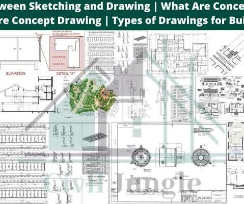
Conceptual Sketches are freehand sketches that are used by designers such as architects, engineers, designers as a quick and simple way. Architecture Concept Drawing. An architecture concept drawing is a technical drawing of a building (or building project) that falls within the definition of architecture. Perspective.
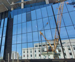
Technological advancements in curtain wall design tools, materials, prototyping, and fabrication techniques offer new avenues for achieving these lofty design and performance goals. The architectural design of curtain walls must be developed alongside increasing demand for high-performing, energy-efficient solutions.
The shop drawing is a drawing or collection of set of drawings, diagrams, illustrations, schedules, and other data or information specifically generated or assembled by the contractor, supplier, manufacturer, subcontractor, or fabricator to demonstrate some portion of the work for the approval of architect or engineer.
This construction video shows the detailed process for structural steel fabrication automatically. Steel fabrication is the process for developing metal structures through cutting, bending, and assembling processes. It is a value added procedures that engrosses the construction of machines and structures out of several raw materials.
A note from the engineer of record on an approved shop drawing for San Francisco's Salesforce Transit Center appears to have initiated an instruction to the steel fabricator to cut two 2-in. holes in the bottom flanges of the hub's built-up plate girders.
Built on the familiar AutoCAD platform, Advance Steel helps provide engineering and detailing professionals the tools needed to model the details necessary for their structures. Easy Access to Fabrication Data. We’ve also made it easier to access customized fabrication data. Out of the box drawings.
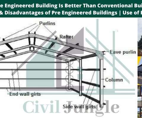
In this article, you will get to know about pre-engineered buildings, its components , advantages and disadvantages. The PEB full form is Pre-Engineered Buildings. The Buildings which are Engineered at the factory and assembled at the site are known as pre-engineered buildings. Components of Pre Engineered Buildings.
Plans are like a set of drawings or two-dimensional diagrams that are used to narrate a place or object or to communicate building or fabrication instructions which are drawn or printed on paper and can take the form of a digital file. So these design drawings can be categorized as: • Feasibility studies. Concept drawings.
The metal should have good workability but also keep its strength during fabrication. Green part in the drawing represent restraint fixing and blue part as load bearing fixing. Non standard materials are difficult to purchase and also very expensive.
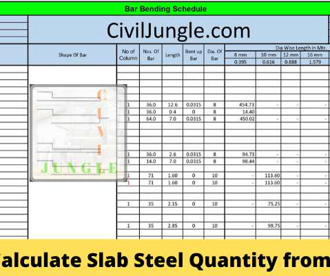
For cutting and bending purposes, schedules should be provided as separate A4 sheets and not as part of the detailed reinforcement drawings. • The form of bar and fabric schedule and the shapes of the bar used should be in accordance with BS 8666. • Estimation of steel quantity is an essential skill of any civil engineer.
Servinsky Engineering, PLLC , a federal court has held that the individual engineer who sealed the drawings and designed the system could be dismissed from the case. The firm (owned by the individual engineer) was hired to design a fabric covered farm building. In a recent Virginia case, McConnell v.
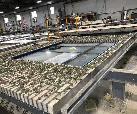
This is the third blog post in a series that discusses the advantages of working on concrete projects in a BIM process for structural engineers. Segmentation is dictated by engineering, architectural, or fabrication requirements, and its reinforcement is determined by the structural engineer.
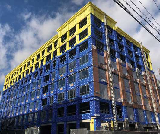
Prefabricated wall panels are individually manufactured in an offsite fabrication shop, complete with exterior cladding and fenestration, anchor system, water/air/vapor barrier(s) and flashing, insulation , and the structural framing. With panelized wall systems, all the materials, tools, and large dumpsters are at the fabrication shop.
Drawings have been used by designers for centuries to communicate ideas to the construction trades. Until recently, those drawings were produced by hand, but in the last 25 years or so, computers have become the primary tool people use to produce construction documents. BIM & Pre-Fabrication.
The submittals include samples, drawings, project data, material listings, quality assurance, etc. A good example is the shop drawing, which provides detailed plans for fabrications that are completed off-site. The illustrations allow contractors or fabricators to know what on-site teams want and what materials are needed.
The submittals include samples, drawings, project data, material listings, quality assurance, etc. A good example is the shop drawing, which provides detailed plans for fabrications that are completed off-site. The illustrations allow contractors or fabricators to know what on-site teams want and what materials are needed.
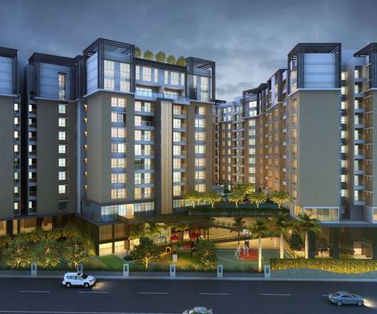
The possibilities for mass-timber are a growing trend and new code provisions have allowed for taller, bigger buildings made of large-format engineered wood, in some cases up to 18 stories or 270 feet tall. For as much criticism as the five-over-one model draws at times, there is nothing wrong with the building type in and of itself.
The submittals include samples, drawings, project data, material listings, quality assurance, etc. A good example is the shop drawing, which provides detailed plans for fabrications that are completed off-site. The illustrations allow contractors or fabricators to know what on-site teams want and what materials are needed.
Below are the top five anticipated engineering and skilled labor shortages according to a survey of 2,223 construction industry professionals. Many of these jobs involve heavy construction or engineering. Laurence Shatkin, author of 21st Century Jobs , believes that demand for civil engineers will spike 24.3
Real property owners, architects, engineers, and builders all would profit greatly from just applying “Change Management 101” effectively as a priority. The latter includes all internal personnel and departments as well as all external services providers (architects, engineers, contractors, consultants, etc.). Diekmann, J.
Reinforcement Detailing or Rebar detailing is a detailed construction engineering process normally accomplished by the Rebar fabricators, structural engineering consultants or the contractors for generating ‘shop/placing’ drawings or shop drawings and bar bending schedule of steel reinforcement for construction.
Shop drawings must be created, approved, and coordinated with other elements of the building, and, therefore, this process should ideally begin eight to 12 weeks before construction and panel fabrication starts.
s Construction Engineering Services (CES) team was awarded with a CRSI Honors for their detailing efforts in Revit. The Martin/Martin CES team has innovatively addressed the issue of fragmented fabricationdrawing production that design and construction teams consistently encounter with today’s increasingly tight project delivery schedules.
The software offers huge benefits to Structural engineering professionals to speed up the process for design, steel detailing, steel fabrication, and steel construction. Steel shop drawings Apply adjustable templates to produce superior-quality drawings. AutoCAD Plant 3D interoperability Incorporate real-time workflow.
Updated Autodesk Structural Fabrication Suite helps advance connected BIM-based steel design and construction workflows. Integrated tools for steel design and construction The updated Autodesk Structural Fabrication Suite has been enhanced to support better connected BIM-based steel design and construction workflows.
.; Cam Featherstonhaugh, AIA, CDT, associate, truexcullins Architecture + Interior Design; and Michael Chambers, FAIA, FCSI, CCS, associate vice-president, HGA Architects & Engineers were on the panel that was chaired by Mark Dorsey, CAE, FASAE, CEO of CSI. Michael Chambers. Cam Featherstonhaugh.
Project teams have traditionally designed using 2D drawings, leaving room for misinterpretation and error between collaborating teams. This siloed process also meant drawings could only be reviewed one at a time, leading to further pre-construction delays. Design changes and fabrication defaults reduced.
Stephen Blumenbaum, PE, SE, Walter P Moore Contractors Designers Designers / Specifiers / Landscape Architects Engineers Facility Managers Architects Building Owners AEC Tech BIM and Information Technology Building Tech Structural Materials Steel Buildings Today’s fast-paced world of design and construction is fractured. Blumenbaum, PE, SE.
We’re excited to share this great customer story from UK based fabricator TSI Structures. They used BIM-based workflows between Autodesk Revit and Advance Steel to reduce their anticipated schedule time by approximately 20 percent. Read more.
The submittal log includes information provided to the architect asking for approval for certain materials and equipment before they’re fabricated and sent to the project site. Construction submittals may include thousands of line items such as color charts, material data, samples, color and finish selections, shop drawings, and more.
Its service offering covers turnkey engineering, full-fledged integrated digital delivery (IDD), and construction and project management encompassing design-and-build; but also real estate development, leasing, and asset management. BIM design changes and fabrication defaults reduced. 40% improvement in QC process (cutting from 2.5
During the project process from design to detailing, there are many discussions between engineer, detailer, and fabricator about how to connect the multi-material framing elements like beams, columns, and bracings. If required, the connection between framing steel elements can be extended with detailed steel connections.
Simplified Acquisition of Base Engineer Requirements (SABER) contracts provide a streamlined means to complete construction projects estimated at less than 750K. Contracting personnel and civil engineers are encouraged to adapt their SABER-like acquisitions and processes to meet their local needs and the local environment.
We also recognize that not all companies have the engineering resources or time to build custom integrations. Fortunately, you can overcome these hurdles by using ACC Connect to sync drawings, field reports, and documents in the cloud. Project managers and project engineers have their work cut out for them.
So, the fabric will make you feel terribly hot, clammy, and uncomfortable on a summery day. Now, let’s have a deep look into the fabric. Nylon fabric is made after numerous processes. These fibers undergo a process called drawing where they are wound into another spool. Nylon fabrics have a huge fan base.
comes with some advanced features like importing drawing data from engineering tools and inserting and controlling attachments inside the application. construction construction material Engineers labour News' The latest version of Jovix (2014.2)
In construction, a Request For Information (RFI) seeks the clarification of plans, drawings, specifications, and agreements. During the construction process, the contractor encounters a discrepancy between the architectural plans and the structural drawings.
ABT Netherlands, a multi-disciplinary consultancy firm, focused on the structural engineering, civil engineering, architectural engineering, moved to BIM-based 3D rebar for concrete reinforced design and fabrication as a result of client demand. They offer a full range of civil engineering and design services.
This construction estimating sheet is not intended for conventional usages the same as an engineering or construction document. Before specific application, the correctness, aptness and suitability should be judged through a proficient professional assessment and authentication by a licensed engineer, architect or other professional.
AIEE: American Institute of Electrical Engineers. ASCE: American Society of Civil Engineers. ASME: American Society of Mechanical Engineers. DWG: Drawing. DWGS: Drawings. ENG: Engineer. ENGR: Engineer. FAB: Fabricate. FABR: Fabricate. FBP: Fabric Panel. ME: Mechanical Engineer.
We organize all of the trending information in your field so you don't have to. Join 116,000+ users and stay up to date on the latest articles your peers are reading.
You know about us, now we want to get to know you!
Let's personalize your content
Let's get even more personalized
We recognize your account from another site in our network, please click 'Send Email' below to continue with verifying your account and setting a password.


Let's personalize your content