This site uses cookies to improve your experience. To help us insure we adhere to various privacy regulations, please select your country/region of residence. If you do not select a country, we will assume you are from the United States. Select your Cookie Settings or view our Privacy Policy and Terms of Use.
Cookie Settings
Cookies and similar technologies are used on this website for proper function of the website, for tracking performance analytics and for marketing purposes. We and some of our third-party providers may use cookie data for various purposes. Please review the cookie settings below and choose your preference.
Used for the proper function of the website
Used for monitoring website traffic and interactions
Cookie Settings
Cookies and similar technologies are used on this website for proper function of the website, for tracking performance analytics and for marketing purposes. We and some of our third-party providers may use cookie data for various purposes. Please review the cookie settings below and choose your preference.
Strictly Necessary: Used for the proper function of the website
Performance/Analytics: Used for monitoring website traffic and interactions
Steel components like plates, bolts, anchors, shear studs, and welds can now be placed in the 3D model to connect structural members together. Having a more accurately defined design model in Revit also enables a better interoperability with Advance steel for steel detailing and fabrication. Standard and Custom Connections.
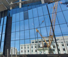
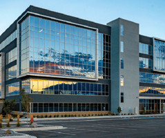
Technological advancements in curtain wall design tools, materials, prototyping, and fabrication techniques offer new avenues for achieving these lofty design and performance goals. The architectural design of curtain walls must be developed alongside increasing demand for high-performing, energy-efficient solutions.
The most common causes of structural failures are: (1) Poor communication between the various design professionals involved, e.g. engineers involved in conceptual design and those involved in the supervision of execution of works. (2) 2) poor communication between the fabricators and erectors. (3)
The shop drawing is a drawing or collection of set of drawings, diagrams, illustrations, schedules, and other data or information specifically generated or assembled by the contractor, supplier, manufacturer, subcontractor, or fabricator to demonstrate some portion of the work for the approval of architect or engineer.
This is the third blog post in a series that discusses the advantages of working on concrete projects in a BIM process for structuralengineers. Segmentation is dictated by engineering, architectural, or fabrication requirements, and its reinforcement is determined by the structuralengineer.
Plans are like a set of drawings or two-dimensional diagrams that are used to narrate a place or object or to communicate building or fabrication instructions which are drawn or printed on paper and can take the form of a digital file. So these design drawings can be categorized as: • Feasibility studies. Concept drawings.
Shop drawings must be created, approved, and coordinated with other elements of the building, and, therefore, this process should ideally begin eight to 12 weeks before construction and panel fabrication starts.
Reinforcement Detailing or Rebar detailing is a detailed construction engineering process normally accomplished by the Rebar fabricators, structuralengineering consultants or the contractors for generating ‘shop/placing’ drawings or shop drawings and bar bending schedule of steel reinforcement for construction.
The software offers huge benefits to Structuralengineering professionals to speed up the process for design, steel detailing, steel fabrication, and steel construction. Steel shop drawings Apply adjustable templates to produce superior-quality drawings.
We’re excited to share this great customer story from UK based fabricator TSI Structures. They used BIM-based workflows between Autodesk Revit and Advance Steel to reduce their anticipated schedule time by approximately 20 percent. Read more.
Updated Autodesk StructuralFabrication Suite helps advance connected BIM-based steel design and construction workflows. Integrated tools for steel design and construction The updated Autodesk StructuralFabrication Suite has been enhanced to support better connected BIM-based steel design and construction workflows.
This cost estimation sheet is very useful for estimating the surface area of structural steel members like beam, grider, column, bolts and welds as well as drawing, fabrication, delivery, welding, painting, erection etc.
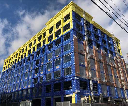
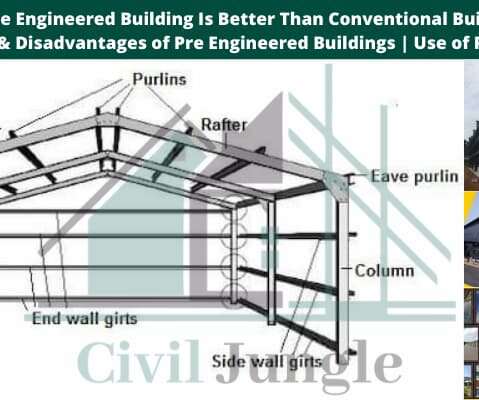
The pre-engineered buildings are widely used for the construction of industrial buildings and warehouses metro stations factories and bridges etc. PEB buildings are the steel structures which are fabricated at the factory to the required size and dimensions. PEB construction is economical and easier in fabrication.
ABT Netherlands, a multi-disciplinary consultancy firm, focused on the structuralengineering, civil engineering, architectural engineering, moved to BIM-based 3D rebar for concrete reinforced design and fabrication as a result of client demand. They offer a full range of civil engineering and design services.
The project team members develop the conceptual estimate during conceptual design stage (generally before the construction drawings and specifications are available) and create a preliminary baseline cost estimate range based on the activities, materials and other sources of expenditure for designing and constructing a specified facility.
Occlusion Culling (2016R2) - The Graphics tab in the Options dialog offers the new setting: Draw visible elements only. Display of walls - Revit will regenerate walls only for those visible within the drawing area. Steel Connections for Revit - This is similar conceptually to what has been done for MEP Fabrication.
Dennis Poon, vice chairman of the Thornton Tomasetti architectural firm and chief structuralengineer of some of Asia’s tallest buildings, told The New York Times that Zhang’s design is feasible but has significant drawbacks.
This week I needed to create some structure from the structuralengineers AutoCAD plans since they were not using Revit. The way I got around the above mentioned error was to open a structural model I received from a different engineer on a different job. Autodesk Fabrication 2013 at Autodesk University 2013.
HVACie extends the existing Industry Foundation Class Coordination View including equipment and system information streamlining construction shop drawing and fabrication. Life-cycle information exchanges have previously been identified in the structural steel domain—an analysis model, a design model, and a detailed model.
HVACie extends the existing Industry Foundation Class Coordination View including equipment and system information streamlining construction shop drawing and fabrication. Life-cycle information exchanges have previously been identified in the structural steel domain—an analysis model, a design model, and a detailed model.
Fabrication methods include using shear blocks to connect vertical and horizontal framing elements or screw-spline construction in which assembly fasteners feed through holes in interlocking verticals and stacking mullions into extruded races in the horizontals. Criteria should be listed on the first sheet of the structuraldrawings.
Giana started her career in civil and structuralengineering, working on both domestic and international programs. For ten years she delivered significant projects, proving her construction prowess and gaining experience across the engineering and construction industry.
We organize all of the trending information in your field so you don't have to. Join 116,000+ users and stay up to date on the latest articles your peers are reading.
You know about us, now we want to get to know you!
Let's personalize your content
Let's get even more personalized
We recognize your account from another site in our network, please click 'Send Email' below to continue with verifying your account and setting a password.


Let's personalize your content